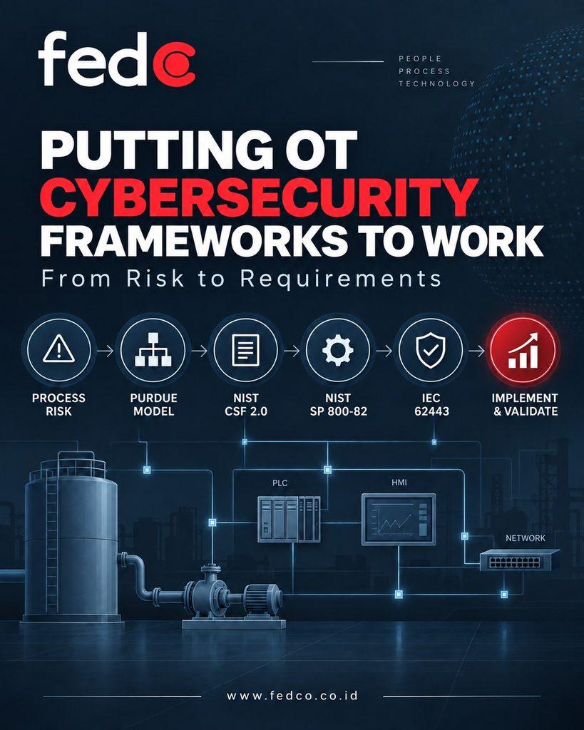
Putting OT Cybersecurity Frameworks to Work: From Risk to Requirements
- cybersecurity program, ICS cyber security, iec 62443, nist csf, nist sp 800-82, ot cyber security, risk assessment, Security Level
OT Cybersecurity Fundamentals – Estimated Reading Time 12 Minutes
Introduction
The previous article described how several cybersecurity references can work together as one practical operating model.
NIST CSF 2.0 helps organizations govern cybersecurity outcomes.
NIST SP 800-82 brings those outcomes into the realities of operational technology.
ISA/IEC 62443 structures IACS risk assessment, architecture, and security requirements.
And where Safety Instrumented Systems are involved, functional-safety requirements must also remain part of the decision.
But an operating model is useful only if it improves decisions about real systems.
Consider a facility that already has:
- An asset inventory
- A network diagram
- Cybersecurity policies
- Assessment findings
- Recommendations
- Several applicable standards
The difficult questions remain:
What should the team do first?
Which proposed security controls are appropriate?
How does the team know when the work is complete?
To answer those questions, we will follow one risk all the way from the physical process to an implemented and validated security requirement.
A Production Scenario: Tank Level and Pump Control
Imagine a facility with a tank receiving liquid through a transfer pump.
A level sensor measures the contents of the tank.
A PLC uses that measurement to control the pump.
Operators monitor the tank level and pump status using an HMI.
A historian records operational information.
An engineering workstation is used to maintain the PLC.
An external vendor occasionally requires remote access for support.
The same general pattern appears throughout OT environments.
Remote connections may support:
- Turbine systems
- Vibration monitoring
- Compressors
- Mining equipment
- SAG mill systems
- Package units
- Process-control systems
- Other specialized industrial equipment
Now consider the following scenario:
An unauthorized person obtains access to the engineering workstation and changes the PLC logic.
The modified logic causes the transfer pump to continue operating after the tank reaches its intended stopping point.
It is tempting to summarize this as:
“The PLC was hacked.”
But that collapses several important events into one statement.
A more useful breakdown is:
Cyber event:
Unauthorized access and an unauthorized change to control logic.
Control-system impact:
The PLC no longer stops the pump as intended.
Process deviation:
The liquid level continues rising.
Potential consequence:
Depending on the real process and safeguards, the result could range from an alarm and controlled shutdown to overflow, equipment damage, environmental release, or another hazardous condition.
The actual consequence cannot be determined from the cyber event alone.
The team must understand the process.
For example:
- Is there an independent high-level alarm?
- Is there a separate shutdown function?
- Is that protective function independent of the PLC?
- Can operators stop the pump locally?
- How quickly does the tank fill?
- What happens if the HMI simultaneously displays incorrect information?
- Would loss of this function affect an SIS or safety instrumented function?
These questions connect cybersecurity with operations, engineering, and—where relevant—process safety.
They also determine which cybersecurity measures deserve priority.
Step 1 — Define What Is Being Assessed
Before assessing risk, define a clear boundary.
“Assess the plant”
is usually too broad for the first useful risk decision.
A better starting point might be:
“Assess the tank and transfer-pump control system.”
The system could include:
- Level sensor
- Field connections
- PLC
- Control logic
- HMI
- Engineering workstation
- Network equipment
- Historian interface
- Vendor remote-access path
- Relevant alarm systems
- Relevant protective or safety functions
In ISA/IEC 62443-3-2 terminology, this is the System under Consideration, or SuC.
Defining the SuC does not mean ignoring everything outside the boundary.
External dependencies must also be identified.
For example:
- Does the engineering workstation depend on an external identity service?
- Is time synchronization provided from another OT zone?
- Does the historian communicate through another network?
- Does vendor access pass through enterprise infrastructure?
- Are backup available (onsite/offsite – verified/validated)?
- Are any safety-related systems connected to the SuC?
The immediate output should be a shared description of:
- What the system does
- What it contains
- Where its boundary lies
- What it depends on
- Who owns it
Step 2 — Map the Architecture and Required Communications
The Purdue Model can help organize the architecture and identify trust boundaries.
The physical process and field devices sit closest to the equipment.
The PLC performs basic control.
The HMI supports operator supervision.
The engineering workstation provides configuration and maintenance capability.
The historian supports operational data needs.
Vendor access begins outside the production environment and crosses toward the control system through one or more intermediary systems.
But identifying Purdue levels is not enough.
The more useful question is:
Who communicates with whom and why?
For every important connection, determine:
- Which systems communicate?
- What operational purpose does the connection serve?
- Which system initiates the communication?
- What protocols or services are required?
- In which direction does information flow?
- Is communication continuous or only required during maintenance?
- Who owns the connection (remember the “owner” term)?
- Who approves it?
- What happens if it fails?
- What happens if it is misused?
Vendor access deserves particular attention.
The statement:
“The vendor needs access to the PLC.”
is not yet a complete operational requirement.
What does the vendor actually need to do?
- View diagnostic information (using which credential)?
- Access an HMI (for what purpose)?
- Access the engineering workstation (is it necessary)?
- Upload a configuration file (any backup made prior the changes)?
- Change controller logic (is it aligned with MoC/project document if any)?
- Update firmware (tested vs. untested)?
- Retrieve logs?
These activities may require very different permissions.
The documented architecture should also be compared with reality.
A diagram may look correct while the actual facility contains:
- Temporary maintenance connections
- Forgotten modems
- Old VPN routes
- Shared accounts
- Dual-homed workstations
- Unmanaged switches
- Vendor-created connections
Architecture discovery must describe the system that exists—not merely the system that was designed.
Step 3 — Describe the Risk in Process Terms
Once the system and communications are understood, describe a credible risk scenario.
For example:
Unauthorized access to the engineering workstation could allow an unapproved modification of PLC logic, causing the transfer pump to continue operating beyond its intended stopping condition. Depending on independent safeguards and operator response, this could produce an operational interruption or harmful process consequence.
This statement is more useful than:
“The engineering workstation could be hacked.”
It provides a chain:
→ Cyber event
→ Control-system impact
→ Process deviation
→ Consequence
The team can then assess the scenario using its established risk methodology.
The assessment should consider:
- Potential consequence
- Exposure path
- Existing safeguards
- Independence of safeguards
- Required access
- Threat assumptions
- Operational assumptions
- Uncertainty
Uncertainty should be documented rather than guessed away.
If the team does not know whether a high-level alarm is independent of the PLC, that is not a small documentation problem.
It is something to investigate.
The purpose of the risk assessment is to determine:
- Which risks require treatment and what protection is appropriate –
It is not to assign the highest possible security level to every asset.
Step 4 — Use NIST CSF 2.0 to Organize the Desired Outcomes
NIST CSF 2.0 provides a common language for organizing the work across six Functions:
Govern → Identify → Protect → Detect → Respond → Recover
Applied to this scenario, each Function creates practical questions.
Govern — Who Makes the Decisions?
- Who owns the control system?
- Who authorizes vendor access?
- Who approves logic changes?
- Who accepts temporary cybersecurity risk?
- Who decides whether production can continue?
- If a safety-related system is affected, who represents process safety?
Operations, engineering, cybersecurity, management, vendors, and safety personnel may all have roles.
Those responsibilities should be established before an urgent event forces the organization to decide under pressure.
Identify — What Must We Understand?
The organization needs an accurate view of:
- Assets
- Software
- Accounts
- Connections
- Dependencies
- Process functions
- Engineering capabilities
- Vendor relationships
An inventory becomes more useful when it explains the function and consequence of an asset—not merely its IP address and model number.
A critical question in this example is:
Which systems can modify PLC logic?
There may be more than one.
Protect — What Should Reduce the Risk?
Possible outcomes include:
- Restrict engineering access
- Limit vendor privileges
- Control when remote access is available
- Require approval for logic modifications
- Protect approved configurations
- Limit communication paths
- Maintain trusted backups
But statements such as:
“Apply least privilege”
remain objectives until someone determines what each person actually needs to do.
A vendor who only needs diagnostic visibility should not automatically receive the same permissions as an engineer authorized to modify control logic.
Detect — How Would We Know?
The facility may require visibility into:
- Vendor remote sessions
- Engineering-workstation logins
- PLC programming activity
- Controller configuration changes
- Unexpected network communication
Detection also requires operational context.
An alert saying:
“PLC configuration changed.”
has limited value if nobody can determine whether the change was authorized maintenance or suspicious activity.
Respond — What Happens Next?
OT incident response must coordinate cyber investigation with process management.
Operators may need to confirm:
- Actual tank level
- Pump behavior
- Alarm status
- Protective-function availability
Engineers may need to compare current PLC logic against an approved version.
The response team must avoid actions that could create a more serious operational problem.
For example, disconnecting a system without understanding its process function could remove visibility or disrupt a protective dependency.
Recover — How Is Trusted Operation Restored?
Recovery may require:
- Approved controller logic
- Configuration integrity verification
- Tested restoration procedures
- Engineering validation
- Process validation
- Defined criteria for returning equipment to service
Recovery is not complete merely because the workstation boots successfully.
Recovery is complete when:
“The process has returned to an accepted operating condition and the restored configuration is trusted.”
Step 5 — Test Proposed Measures Against OT Reality
NIST SP 800-82 helps teams evaluate proposed safeguards in the context of OT performance, reliability, safety, and operational constraints.
Suppose the organization proposes stronger authentication for engineering access.
The idea may be sound.
But engineering must still ask:
- Is the mechanism supported?
- What happens during an outage?
- Does authentication depend on another network or server?
- What happens if that service is unavailable?
- Is emergency access required?
- How is emergency access controlled and reviewed?
Now suppose the organization proposes blocking direct vendor-to-PLC communication.
Again, the principle may be sound. But the team still needs to determine:
- What maintenance functions are actually required?
- Through which approved system should they occur?
- Can the new access design support those functions?
- Can it be tested safely?
- What is the rollback plan?
The same discipline applies to:
- Patching
- Endpoint protection
- Firewalls
- Application whitelisting
- Backup systems
- Monitoring software
- Authentication
- Network changes
For every measure, ask:
What risk is this control intended to reduce?
What system behavior could it change?
How will engineering and operations validate it?
What is the rollback plan?
What will be monitored after deployment?
These questions do not weaken cybersecurity.
They make cybersecurity appropriate for the system it must protect.
Step 6 — Use ISA/IEC 62443 to Structure the Requirements
ISA/IEC 62443 can then help translate the assessed risk into system architecture and explicit security requirements.
The team can:
- Group assets with common security requirements into zones.
- Identify necessary communication between zones.
- Define conduits.
- Establish security requirements.
- Determine appropriate target security levels based on risk.
- Assign lifecycle responsibilities.
A zone should not automatically be equated with a Purdue level.
Two systems at the same Purdue level may have different security requirements.
Conversely, architecture should not be created simply to make the drawing resemble a reference model.
For the tank and pump system, the team may decide to separate:
- Production-control functions
- Engineering functions
- Vendor remote-access services
- Other operational systems
If an SIS or safety-related system is involved, it may warrant treatment as a separate zone with distinct requirements based on the risk assessment and functional-safety lifecycle.
The resulting requirements can become concrete.
For example:
- Remote vendor access requires an approved request.
- Remote access is enabled only for a defined period.
- Vendor activity reaches OT through the approved access path.
- Only authorized roles may modify PLC logic.
- Every logic change has an identified requester.
- Every logic change has an approver and documented purpose (MoC).
- Relevant changes are tested before acceptance.
- An approved version of PLC logic is retained.
- The approved logic can be restored.
- Relevant access and change activity can be reviewed during an investigation.
Notice that these statements describe required capabilities and practices.
Purchasing a firewall does not, by itself, demonstrate that these requirements have been satisfied.
Step 7 — Implement, Validate, and Record Remaining Risk
Once requirements have been agreed, the organization can design and implement the measures.
Operations & Maintenance and Engineering departments should participate in validation because they understand the behavior that must remain available.
Validation should answer two fundamental questions:
1. Does the measure provide the intended cybersecurity capability?
and
2. Does the system continue performing its operational function safely and reliably?
For example, the organization could verify that:
- An approved vendor can perform the required maintenance activity.
- The vendor can use only the approved path.
- An unauthorized account cannot modify PLC logic.
- Remote access can be disabled after the maintenance period.
- Relevant activity is recorded.
- An approved PLC logic version can be restored.
- Operations retain necessary visibility.
- Required protective functions remain available.
The organization should retain evidence appropriate to the risk decision.
This may include:
- Updated architecture diagrams
- Approved requirements
- Access records
- Logic-change records
- Configuration records
- Test results
- Backup and restore evidence
- Documented exceptions
- Risk acceptance
- Management-of-Change records where applicable
Target (SL) Does Not Mean Achieved (SL)
This distinction is important.
A target security level expresses the security level called for by the risk assessment.
It does not prove that the installed system has actually achieved it.
The implemented architecture, technical controls, procedures, people, maintenance practices, and operating conditions still need to be evaluated.
The difference can be summarized as:
Target → What the system needs
versus
Achieved → What the implemented system demonstrably provides
The same principle applies beyond security levels.
A written policy does not prove that remote access is controlled.
A backup does not prove that recovery works.
A firewall does not prove that only necessary communication is possible.
A monitoring platform does not prove that meaningful events will be detected and acted upon.
Validation closes the gap between intention and reality.
Remaining Risk Still Exists
Security measures rarely reduce risk to zero.
Some risk may remain after planned improvements are completed.
The asset owner should understand:
- What remains
- Why it remains
- Which assumptions support the decision
- Whether additional treatment is required
- Who accepts the remaining risk (it also depends on the risk appetite)
The decision should also be revisited when:
- Process conditions change
- Architecture changes
- New remote connections are introduced
- Suppliers change
- Threat exposure changes
- Safeguards are modified
- A system reaches a different lifecycle stage or
- System compromised
Risk assessment is not a one-time document, but it is part of system operation.
One Risk, Several Complementary References
The pieces now fit together.
The physical process tells us what can go wrong and what the consequences may be.
The Purdue Model helps us understand architecture and trust boundaries.
NIST CSF 2.0 helps define, govern, and communicate the cybersecurity outcomes.
NIST SP 800-82 Rev. 3 helps determine how security measures should be applied in real OT conditions.
ISA/IEC 62443 helps define the SuC, assess system risk, structure zones and conduits, establish requirements, and assign lifecycle responsibilities.
Functional-safety practices and IEC 61511, where an SIS is involved, help ensure that cybersecurity changes do not compromise the safety functions that protect the physical process.
Implementation then continues through:
→ Design
→ Testing
→ Validation
→ Operation
→ Monitoring
→ Reassessment
These references do not need to compete. They support different parts of the same decision.
Key Takeaway
The purpose of an OT cybersecurity framework is not to produce more framework documentation.
Its purpose is to improve decisions about real operational systems.
Start with:
“A defined process and a credible scenario.”
Trace the path:
→ Cyber event
→ Control-system impact
→ Process deviation
→ Consequence
Then determine:
- Who owns the risk
- What cybersecurity outcomes are required
- How controls must be adapted to OT
- Which architecture and requirements are appropriate
- Whether functional safety is affected
- How controls will be implemented
- How their effectiveness will be validated
- What evidence will be retained
- What risk remains
That is how a collection of frameworks becomes a practical OT cybersecurity operating model.
References
- NIST Cybersecurity Framework 2.0
- NIST SP 800-82 Rev. 3 — Guide to Operational Technology Security
- ISA/IEC 62443 Series
- IEC 61511 where functional safety and Safety Instrumented Systems are applicable