Inside the Purdue Model: Mapping the OT Architecture
- ICS cyber security, ics security, ics security assurance, ics security training, OT secure architecture, purdue model, purdue model architecture, scada security training
OT Cybersecurity Fundamentals – Estimated reading time: 7 minutes
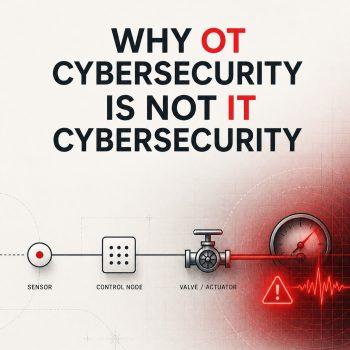
After understanding why OT cybersecurity is different from IT cybersecurity, we move on to the next thing which is represented by this simple question:
Where do all these systems sit, and how do they connect?
The Purdue Model is one of the most widely used ways to answer that question. It gives us a common architectural language for discussing industrial systems, data flows, ownership, and trust boundaries.
It is not a mandatory network blueprint. It is a reference model, a practical way to organize the conversation before making cybersecurity, segmentation, or risk-management decisions.
Why Architecture Matters in OT Cybersecurity
An OT environment is rarely one isolated controller or one operator workstation. It is a connected system of field devices, controllers, supervisory systems, engineering tools, operational applications, historian database, enterprise services, vendors, and remote users.
Without an architecture view, it is difficult to answer important questions:
- Which systems directly affect the physical process?
- Which connections cross from business IT into OT?
- Which systems require remote access?
- Where should controls such as firewalls, data diode, industrial monitoring, and access restrictions be placed?
- Which pathways could allow an issue in one part of the environment to affect another?
The Purdue Enterprise Reference Architecture, often called the Purdue Model, helps organize these questions into logical levels.
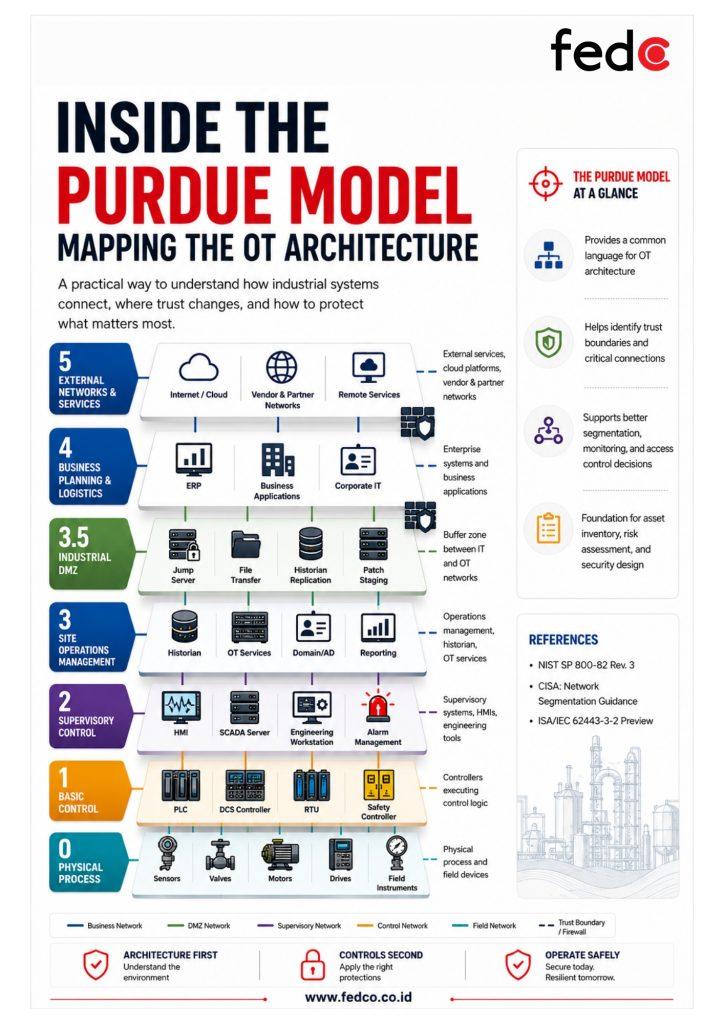
The Purdue Model at a glance
| Level | Primary purpose | Typical examples |
| Level 0 | Physical process | Sensors, actuators, valves, motors, drives, field instruments |
| Level 1 | Basic control | PLCs, RTUs, DCS controllers, safety controllers |
| Level 2 | Supervisory control | HMIs, SCADA servers, engineering workstations, OT domain services (if it is designed to be separated from Level 3 domain controller) |
| Level 3 | Site operations management | Historians, patch-management servers, OT domain services (to cover level 3 only, or another level such as Level 2, if it is designed as per mentioned – regardless Zone and Conduit SL-T profiles), reporting and operations applications |
| Level 3.5 | Industrial DMZ | Jump servers, secure file-transfer services, replication servers, proxy services |
| Level 4 | Business planning and logistics | ERP, business applications, corporate identity services, office IT |
| Level 5* | External networks | Internet, cloud services, partner networks, remote external services |
* Level 5 and Level 3.5 are commonly used extensions in modern diagrams. The original Purdue reference model is generally described through Levels 0 to 4.
Level 0: The Physical Process
Level 0 is where the physical world is measured or changed.
Examples include:
- Pressure, temperature, flow, and level sensors
- Control valves and actuators
- Motors, pumps, drives, and relays
- Field instruments and analyzers
At this level, information becomes action. A sensor measures a process condition; an actuator or valve changes the process based on a command (set point or manual driven by human interface, or bypass by safety system to ensure safety operations in place).
From a cybersecurity perspective, this level matters because an inaccurate measurement, unavailable signal, or unintended command may have a direct effect on process control.
Level 1: Basic control
Level 1 contains the systems that execute the core control logic.
Typical assets include:
- PLCs
- RTUs
- DCS controllers
- Safety controllers
- Remote I/O systems
A controller receives input from Level 0 devices, applies programmed logic, and sends output to field equipment.
For example, a PLC may receive a tank-level measurement and decide whether to start or stop a pump. A DCS controller may regulate temperature by adjusting a control valve. A safety controller may initiate a protective action when a hazardous condition is detected.
Because these systems can directly influence the process, changes to logic, firmware, communications, or configuration, it requires careful engineering control and operational validation.
Level 2: Supervisory control
Level 2 gives operators and engineers visibility of the process and tools to supervise it.
Typical systems include:
- Human-Machine Interfaces (HMIs)
- SCADA servers
- Engineering workstations
- Alarm-management systems
- Operator terminals
An HMI may allow an operator to view a process trend, acknowledge an alarm, change an approved setpoint, or issue a command. An engineering workstation may allow an authorized engineer to configure or maintain controllers.
Level 2 is often a high-value target because it combines process visibility, control capability, and privileged access. Losing an HMI may affect operator awareness. Compromise of an engineering workstation may affect the integrity of controller configuration or logic.
Level 3: Site Operations Management
Level 3 contains systems that support the operation and management of the industrial site.
Typical systems include:
- Historians
- OT application servers
- Patch-management and update services
- OT identity and authentication services
- Backup systems
- Reporting platforms
- Manufacturing execution or operational-support services
Level 3 often connects the real-time control environment to broader operational needs. For example, a historian may collect data from control systems for analysis, reporting, quality investigations, maintenance planning, or production optimization.
These systems are important because they frequently exchange information with both supervisory systems below (L2 and L1) and enterprise systems above (L4 through L3.5). Their connections should be documented and deliberately controlled.
Level 3.5: The Industrial DMZ
The industrial DMZ, often called Level 3.5, is a buffer zone between enterprise IT and the core OT environment.
It is designed to reduce the need for direct connections between business system and control system.
Common DMZ services include:
- Secure remote-access jump servers
- File-transfer and malware-protection services
- Historian replication servers
- Patch-staging services
- Proxy or application-gateway services
- Data brokers and reporting interfaces
The design principle is straightforward: systems in the enterprise network should not communicate directly with critical OT assets unless there is a justified, protected, and monitored pathway.
CISA describes segmentation as a physical or virtual approach that divides a network into controlled segments. It notes that properly implemented DMZs and firewalls can help protect high-value OT assets while allowing necessary communications. CISA’s segmentation guidance
Level 4: Business Planning and Logistics
Level 4 contains enterprise IT systems that support business operations.
Examples include:
- Enterprise Resource Planning (ERP) platforms
- Corporate email and collaboration systems
- Business databases
- Corporate identity services
- Finance, procurement, and planning applications
- Office networks
Level 4 systems may need data from OT for production reporting, maintenance planning, inventory tracking, scheduling, or business analytics.
That business need is legitimate. The cybersecurity challenge is ensuring that necessary data flows do not become uncontrolled pathways into the OT environment.
Level 5: External Networks and Services
Modern diagrams often add a Level 5 to represent external services and networks, such as:
- The internet
- Cloud platforms
- Vendor-managed services
- Partner networks
- Remote monitoring platforms
- External data services
This layer reflects modern realities. However, it also reinforces the importance of carefully governed remote access, secure data exchange, supplier management, and visibility of external dependencies.
The Real Value of the Model: Trust Boundaries
The Purdue Model is useful because it identifies where trust should change.
A connection between a controller and a local HMI has a different purpose and risk profile from a connection between an ERP system and a production historian. Similarly, a vendor connection should not have the same access path as a control-room operator.
At each boundary, teams should ask:
- Is this communication necessary?
- Which systems need to communicate?
- Which protocol, port, direction, and frequency are required?
- Who owns and approves the connection?
- How is the traffic monitored?
- What happens if the connection fails or is misused?
IEC 62443 provides a related architectural concept: partitioning an industrial automation and control system into zones with common security requirements, connected through controlled conduits. IEC 62443-3-2 uses this approach as part of defining the system, assessing risk, and documenting security requirements. ISA/IEC 62443-3-2 preview
Do not treat Purdue as a rigid blueprint. Real OT environments rarely match a clean reference diagram. Common examples include:
- Flat networks created before segmentation was a design priority
- Legacy systems with undocumented dependencies
- Direct links between enterprise and plant networks
- Vendor remote-access connections added for support purposes
- Wireless or IIoT devices introduced outside the original architecture
- Cloud-based data collection or analytics platforms
- Temporary engineering connections that became permanent
These conditions do not automatically mean the environment is unsafe. They do mean the architecture needs to be understood before controls are changed.
A poorly planned segmentation project can interrupt production just as easily as an uncontrolled connection can increase risk. The right approach is to document flows, involve operations and engineering teams, validate dependencies, implement changes in phases, and maintain a rollback plan.
A Practical Mapping Exercise
A useful first activity is to map one production area or process line rather than attempting the whole facility at once.
Start with a simple flow:
Sensor → PLC → HMI → Historian → Business reporting system
Then document:
| Question | Example answer |
| What does the asset do? | PLC controls pump start/stop logic |
| Which Purdue level best represents it? | Level 1 |
| What does it communicate with? | HMI, engineering workstation, remote I/O |
| Why is the communication needed? | Operations, maintenance, and process control |
| What is the direction of flow? | Defined control and monitoring traffic |
| Who owns the asset and connection? | Control engineering / OT operations |
| What would happen if the connection failed? | Loss of visibility, delayed response, or degraded control capability |
This exercise produces more than a diagram. It begins an asset inventory, dependency map, and foundation for later asset criticality and risk assessment.
Key Takeaway
The Purdue Model is not a one-size-fits-all architecture. It is a shared language for understanding how physical processes, control systems, operational applications, business systems, and external services connect.
Before selecting cybersecurity controls, map the environment. Know where systems sit, which connections are necessary, who owns them, and where trust boundaries need to be enforced.
References